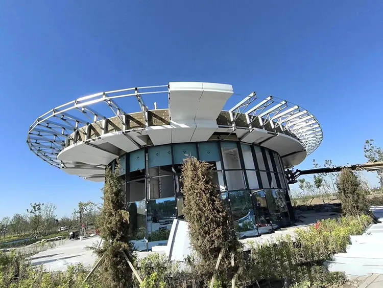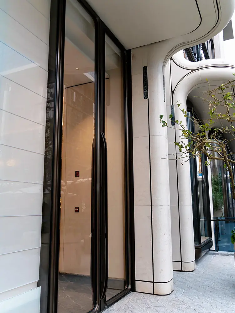
Curved aluminum cladding panels are not difficult because the word “curved” is unusual. They become difficult when the drawing does not say what kind of curve must be made, where it starts and ends, or how one panel must meet the next.
For a useful quotation, decide four things first: whether the surface is single-curved or double-curved, what product form is being curved, how the geometry is dimensioned, and where the joints may appear. Then the fabricator can review the material, forming route, support and sample plan. Asking only “What is your minimum radius?” is not enough.
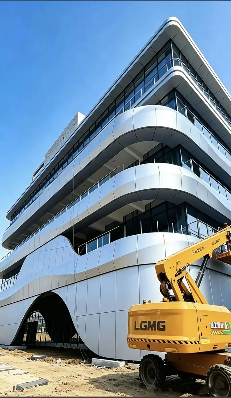
Start with the shape: single curve or double curve?
A single-curved panel bends in one main direction. Think of a flat sheet wrapped around part of a cylinder. Straight lines can still run along the other direction. Barrel vaults, rounded corners and many curved soffit bands fit this category.
A double-curved panel changes in two directions at the same time. A dome-like, saddle-like or flowing free-form surface is a common example. A flat sheet cannot take that shape cleanly by simple rolling alone; the material and the panel boundaries must be developed more carefully.
| Design question | Single-curved panel | Double-curved panel |
|---|---|---|
| Basic geometry | One main radius or controlled curve direction | Curvature changes in two directions |
| Common starting route | Rolling, bending, stretch forming or a fabricated segmented solution, depending on the panel | Specialized forming, dies, stretch forming, incremental development or smaller faceted segments |
| Drawing input | Radius plus limits, chord and rise, or a full-size profile | Controlled 3D surface, panel boundaries, datums and section cuts |
| Main visual risk | Flat spots, springback, a visible kink at the tangent or inconsistent radius | Twist, local distortion, mismatched edges and a surface that changes between panels |
| Sensible approval | One representative panel including an end condition | A representative multi-panel mock-up including a difficult transition |
Industry fabricators describe double curvature as much more demanding than rolling a sheet into one direction. Zahner’s explanation of Curved aluminum cladding fabrication reference is a useful reference: the geometry has to be developed together with the fabrication method. It should not be treated as a more decorative version of a standard flat panel.
There is also a practical middle route. A design that looks double-curved from normal viewing distance may sometimes be divided into narrower single-curved panels or faceted panels. That can reduce tooling, but it changes the joint pattern and reflected light. The architect should approve that visual trade-off before the quotation is compared.
Define the radius so everyone measures the same curve
“Radius 2000 mm” still leaves questions. Is it the inside radius, outside radius or centerline radius? Does it apply to the finished face, the supporting frame or the theoretical building surface? Where are the tangent points? Does the panel continue as a straight return after the curve?
For a circular arc, a supplier can reconstruct the radius when the straight-line chord c and the midpoint rise, also called sagitta, h are known:
R = c² / (8h) + h / 2
The formula is useful as a cross-check, but it does not replace the drawing. The drawing should mark the chord endpoints, the direction of the rise and the surface to which the radius applies. For a non-circular spline, do not force one radius onto it. Send the 3D model plus agreed section cuts and coordinates.
Include these items on the controlled drawing:
- inside, outside or centerline radius;
- chord length, rise and arc limits;
- tangent points and any straight extensions;
- finished face and viewing direction;
- panel thickness, folds, returns and edge conditions;
- datum, panel ID and orientation;
- joint centerlines and nominal joint widths;
- 2D sections or coordinate points used for inspection.
If the consultant works from a design surface while the fabricator works from the panel face, state the offset between them. Otherwise both drawings can be internally correct and still describe two different curves.
Why there is no universal minimum radius
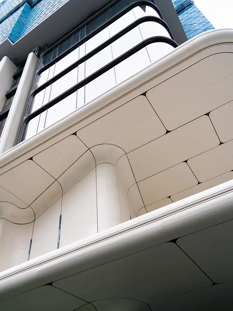
A factory cannot give one honest minimum radius for every “aluminum panel.” The answer changes with the product form, alloy and temper, thickness, panel width, return geometry, perforations, required surface quality, tooling and process sequence.
TRUMPF’s bending-tool guidance notes that bend results depend on factors such as material, sheet thickness and tool radius, and that springback may require compensation. Davi similarly explains in its plate-rolling glossary that springback and the rolling setup affect the result. These are the reasons a radius copied from an unrelated data sheet is not a reliable purchase specification.
The finish matters too. A process that achieves the geometry may still leave pressure marks, facets or local waviness that are unacceptable on a glossy architectural face. A protective film can help during some forming operations, but it cannot turn an unsuitable radius or process into an approved facade surface.
Ask the supplier for a feasibility answer tied to your exact panel, not a marketing number. A responsible response may be:
- feasible with normal production tooling;
- feasible after a representative sample;
- feasible if the panel is divided or the return is changed;
- feasible only with dedicated tooling and a minimum batch;
- not recommended for the specified appearance.
That answer is more useful than a small radius printed without conditions.
Identify the product form before choosing the process
“Curved aluminum cladding” can mean several different things: a rolled solid sheet cassette, a narrow baffle, a curved extrusion, a welded box, a perforated screen or a set of faceted flat panels. They do not use the same manufacturing route.
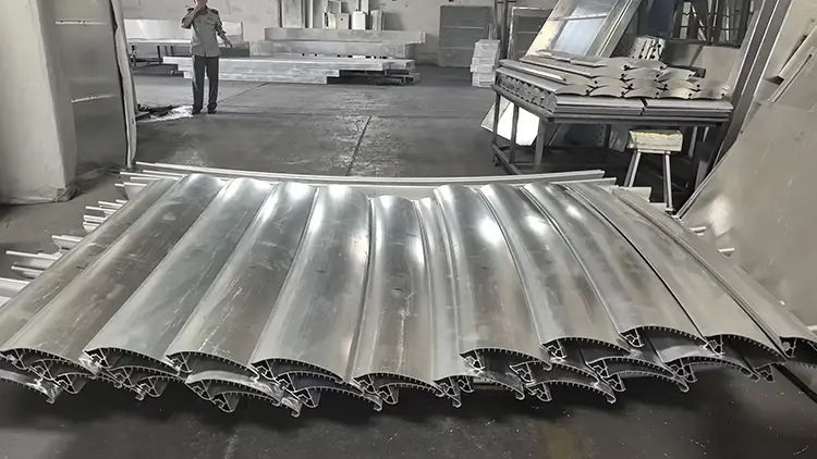
For example, extrusion stretch forming pulls a constant cross-section profile around a die. Sheet stretch forming holds the edges of a sheet while forming it over a contour. Beckwood’s stretch-forming overview distinguishes these two routes. A successful radius for one profile therefore does not prove that a wide solid-aluminum cassette with folded returns can use the same radius.
Common routes include:
- Plate or sheet rolling: a natural starting point for cylindrical single curvature. Roll geometry, material behavior and springback affect the achievable result.
- Press-brake bump forming: a series of small bends can approximate a curve. It may be economical for some concealed or larger-radius work, but visible facets must be judged on a sample.
- Stretch forming: useful for smooth curved profiles and some sheet applications when suitable dies and gripping allowances are available.
- Welded fabrication: separate formed pieces can be joined for deep returns, corners or complex transitions. Weld preparation, grinding and heat distortion then become part of the visual review.
- Faceted panelization: flat or single-curved panels approximate a complex surface. It can simplify fabrication while making joints and reflections more visible.
Do not name the production method in the specification unless the method itself is required. Define the finished geometry, face quality and inspection instead, then let qualified suppliers propose a route and disclose any exceptions.
Panel joints are part of the curve
A smooth digital surface can become awkward when it is split into shippable panels. Panelization should be discussed before the shop drawings are finished, especially around corners, soffits, columns and changing radii.
Check the following on the full elevation or model:
- Put joints where the surface can transition cleanly and where the supporting frame can reach them.
- Avoid a very narrow closing panel unless it is intentional and installable.
- Keep the joint rhythm readable around corners; do not solve each elevation separately and discover a mismatch at the turn.
- Mark tangent lines so a curved panel does not meet a flat panel with an accidental kink.
- Decide whether a joint follows the design grid or the easiest manufacturing split. If those differ, the architect should choose.
- Number panels from one stable datum and keep that orientation through inspection, packing and installation.
For a repeating cylindrical band, one master radius may control many panels. For a free-form facade, adjacent edges may each be unique. In that case, a panel schedule should link every physical panel ID to its model position and drawing revision.
The support frame and installation sequence must use the same geometry
A panel can match its inspection template and still look wrong on the building if the subframe follows another curve. The panel face, bracket locations, rail geometry and joint centerlines need a common datum.
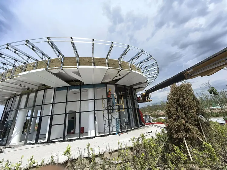
Before production, coordinate:
- survey responsibility and the date of site dimensions;
- allowable adjustment at brackets or cleats;
- fixed and movement points required by the engineered system;
- installation direction and temporary support;
- access for fasteners at tight inside curves;
- replacement access after surrounding panels are installed;
- how site deviation will be reported rather than forced into the panel.
Curving a panel does not prove that the panel or fixing system is adequate for project loads. The project engineer must review the complete assembly for the actual span, support spacing, wind actions and local code. A visual mock-up confirms appearance and fit; it is not a substitute for structural design.
Approve the surface, edges and panel back together
Curved panels can show defects differently from flat panels because reflections travel across the face. Gloss level, metallic color, joint alignment and light direction can make small profile changes noticeable.
Agree how appearance will be judged. Record the viewing distance, light condition and approved sample rather than using only words such as “smooth” or “perfect.” For dimensional inspection, agree whether the factory will use a full-size template, measured stations, laser scan or another project-approved method. State the number and location of checkpoints.
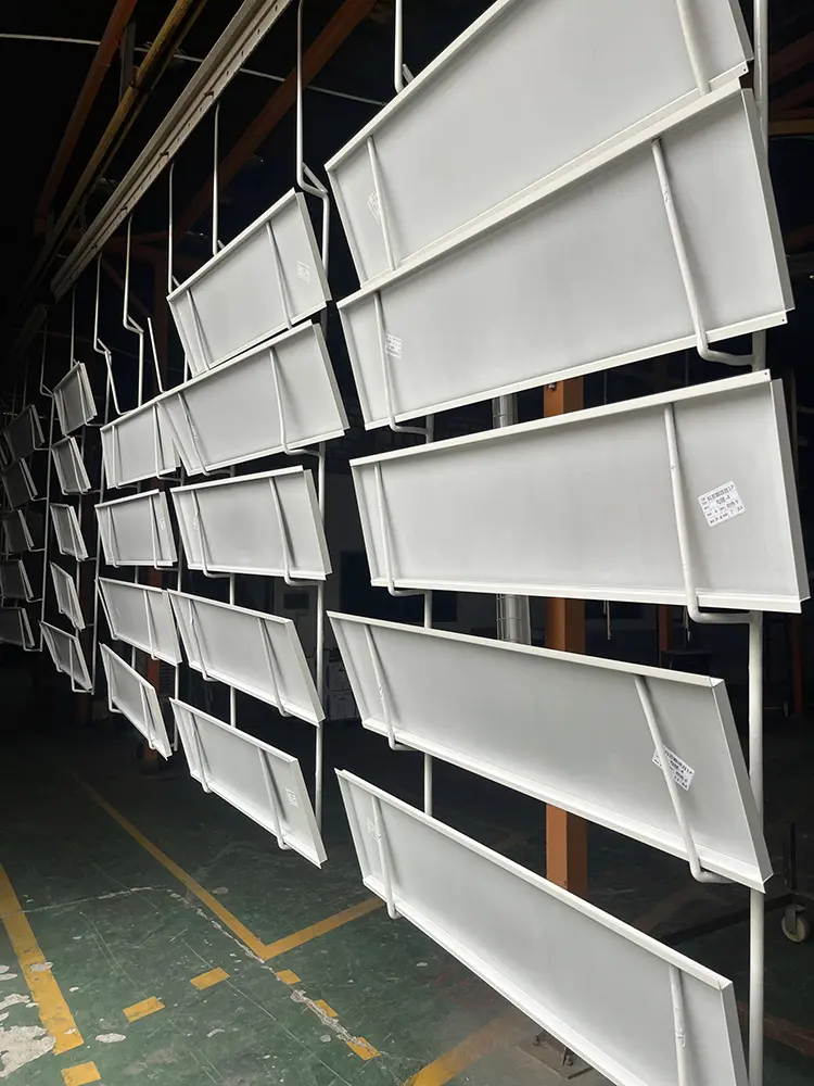
Review the back at the same time:
- folded returns and corner treatment;
- reinforcement layout and how it connects to the skin;
- brackets, cleats, hangers and access for installation;
- drainage or ventilation details where the system requires them;
- panel ID, orientation and drawing revision;
- protection between finished faces during packing.
Coating sequence must also be agreed before the sample is made. Forming after a final finish can damage or mark some surfaces; coating after forming introduces its own hanging, preparation and color-control questions. The right sequence depends on the finish and panel route, so approve a sample made in the proposed sequence rather than a flat color chip.
Use a sample that tests the risky part
A small flat color swatch does not approve a curved cladding panel. The representative sample should include the feature most likely to fail: the tightest proposed curve, a tangent transition, a difficult return, a visible joint, a welded corner or a metallic finish with demanding reflection.
A practical approval sequence is:
- Geometry review: confirm the controlled drawing or model, datums and panel boundaries.
- Process proposal: record the material, forming route, fabrication sequence and any requested design change.
- Representative sample: make the difficult condition in the proposed material and finish.
- Measured check: compare the agreed sections or template points, not only the overall width.
- Visual check: view the sample in relevant light, from the intended direction and with a real joint where possible.
- Approval record: sign the drawing revision, sample ID, color reference and accepted exceptions.
- First-batch check: inspect adjoining panels before the whole order is produced.
For double-curved or highly visible work, the useful mock-up is often more than one panel. A single panel cannot prove that adjacent edges, joint widths and reflections will continue correctly.
What changes the quotation?
Curved-panel price is not simply flat-panel price plus a curve charge. The main cost drivers are the number of unique geometries, forming and checking time, dedicated dies or templates, welding and finishing, rejected trial pieces, reinforcement, 3D coordination, panel size, packing supports and shipment volume.
Separate one-time and repeat costs where possible. Tooling, model development and the first mock-up may be one-time items. Forming, inspection and packing remain per-panel or per-batch costs. Also ask how replacement panels will be made after the first production run. A unique panel without retained geometry or an identification record can be expensive to reproduce.
Compare quotations against the same panel schedule. A low quote may exclude templates, mock-ups, reinforcement, controlled packing or difficult transition pieces. The missing scope usually appears later, when changing the geometry is more expensive.
Where Likton adds useful support
Likton’s general aluminum curtain wall manufacturer guide already explains why custom facade work needs drawing review, panel-back checks, coating coordination, numbering and packing. For curved aluminum cladding, those steps should be tied to the approved geometry rather than presented as general factory claims.
The useful starting point is a fabricability review: identify the product form, flag missing radius information, propose panel divisions, select a representative sample and show what will be inspected before mass production. Likton can also compare the curved scope with the project’s exterior aluminum veneer requirements so that shape, finish, reinforcement and fixing details are quoted together.
This is not a promise that every curve can be made without changes. A good early review should say where a panel needs a different split, a larger radius, a changed return, special tooling or an approved visual compromise. Finding that before coating and shipment is the real service value.
Questions buyers ask before ordering
What is the difference between single-curved and double-curved aluminum panels?
A single-curved panel bends mainly in one direction, like part of a cylinder. A double-curved panel changes in two directions, like a dome or saddle. Double curvature normally needs more detailed 3D development, forming and multi-panel checking.
What is the minimum radius for a curved aluminum panel?
There is no reliable universal number. The practical radius depends on product form, alloy and temper, thickness, panel width, edge returns, perforations, tooling, finish and acceptable appearance. Send the exact drawing and ask for a sample-based feasibility review.
Should I send radius, chord length or arc length?
Send all available information. At minimum, mark whether the radius is inside, outside or centerline, then provide arc limits and tangent points. Chord and rise are useful cross-checks. For a non-circular surface, send the controlled 3D model and section coordinates.
Can flat panels be used to create a double-curved appearance?
Sometimes. Narrow flat or single-curved panels can approximate a complex surface, but they create facets and more joints. Review the appearance from the normal viewing distance and approve a multi-panel mock-up before changing the design.
Should curved panels be formed before or after coating?
The sequence depends on the finish and forming route. Forming can mark a finished surface, while coating a completed shape affects preparation and handling. Ask the supplier to state the full sequence and approve a sample made the same way as production.
Why do curved aluminum cladding panels cost more than flat panels?
The extra work may include model development, unique panel geometry, forming, tooling or templates, springback compensation, welding and finishing, profile inspection, special packing and trial pieces. Ask suppliers to separate one-time development costs from repeated panel costs.
Is one sample panel enough?
It can be enough for a simple repeating single curve. For changing radii, double curvature or a critical transition, use a multi-panel mock-up that includes a real joint and the difficult edge condition.
RFQ checklist for comparable curved-panel quotations
| Include in the RFQ | Why it matters |
|---|---|
| 3D model plus controlled 2D elevations and sections | Gives the supplier both design geometry and dimensions that can be checked |
| Curve type, radius reference, chord, rise, arc limits and tangent points | Prevents different teams from building different interpretations of the same curve |
| Panel IDs, boundaries, joint widths and orientation | Connects fabrication, packing and installation to one panel map |
| Alloy, temper, thickness and product form | Allows the factory to assess the real forming route rather than a generic “aluminum panel” |
| Folded returns, welds, reinforcement and fixing details | Shows features that can restrict forming or affect the finished profile |
| Finish type, color, gloss and proposed process sequence | Controls visible marks, batch appearance and when forming occurs |
| Quantity of each unique panel, not only total area | Reveals repetition, tooling value and the real production mix |
| Profile and visual acceptance method | Replaces vague requests for a “perfect curve” with an agreed check |
| Sample or multi-panel mock-up scope | Tests the tightest curve, tangent, joint and finish before mass production |
| Site survey, installation sequence and adjustment method | Keeps panels, frame and building conditions tied to the same datum |
| Panel numbering, packing supports and replacement records | Reduces mix-ups and protects shaped panels in transport |
| Delivery location and handling limits | Helps the supplier review crate size, support and shipment volume |
To get a useful response, send Likton the drawing package, panel schedule and finish requirement, then ask for three written outputs: the proposed forming route, the conditions that still need confirmation, and the representative sample plan. Approve those before treating the price as final.